Instagram. Snapchat. Photoshop.
All of these applications are used to do image processing. Image processing can be as simple as converting a photo to grayscale and as complex as analyzing a video of a crowd for a specific person. In spite of how divergent these applications are, both of these examples go through the same process from creation to rendering.
There are many ways to process images on your computer or mobile phone, but by far the most efficient is effectively using your Graphics Processing Unit, or GPU. Your phone contains two different processing units, the CPU and the GPU. The CPU is a generalist that has to deal with everything, while your GPU can focus on doing one thing really well, which is doing floating-point math in parallel; it turns out that image processing and rendering is nothing more than doing a lot of floating-point math on the values for the pixels that render to your screen.
By effectively utilizing your GPU, you can increase graphics-rendering performance on your phone by a hundred fold, if not a thousand fold. Being able to filter high-quality live video on your phone is impractical or even impossible without GPU-based processing.
The tool we use to take advantage of this power is a shader. A shader is a small, C-based program written in a shading language. There are many shading languages out there on the market, but the one you should focus on if you are doing OS X or iOS development is the OpenGL Shading Language, or GLSL. You can take the concepts from GLSL and apply them to other, more proprietary languages like the Metal Shading Language. The concepts we are going over here even map well to custom kernels in Core Image, although they use a slightly different syntax.
This process can be incredibly daunting, especially to newer developers. The purpose of this article is to get your feet wet with some foundation information necessary to get you going on your journey to writing your own image processing shaders.
What Is a Shader?
We're going to take a short trip in The Wayback Machine to get an overview of what a shader is and how it came to be an integral part of our workflow.
If you've been doing iOS programming since at least iOS 5, you might be aware that there was a shift in OpenGL programming on the iPhone, from OpenGL ES 1.1 to OpenGL ES 2.0.
OpenGL ES 1.1 did not use shaders — it used what is called a fixed-function pipeline. Instead of creating a separate program to direct the operation of the GPU, there was a set of fixed functions that you used to render objects on the screen. This was incredibly limiting, and you weren't able to get any specialized effects. If you want a good example of how much of a difference shaders can make in a project, check out this blog post Brad Larson wrote about refactoring his Molecules app using shaders instead of the fixed-function pipeline.
OpenGL ES 2.0 introduced the programmable pipeline. The programmable pipeline allowed you to go in and write your own shaders, giving you far more power and flexibility.
There are two kinds of shader files that you must create in OpenGL ES: vertex shaders and fragment shaders. These shaders are two halves of a whole program. You can't just create one or the other; both must be present to comprise a whole shader program.
Vertex shaders customize how geometry is handled in a 2D or 3D scene. A vertex is a point in 2D or 3D space. In the case of image processing, we have four vertices: one for each corner of your image. The vertex shader sets the position of a vertex and sends parameters like positions and texture coordinates to the fragment shader.
Your GPU then uses a fragment shader to perform calculations on each pixel in an object or image, ending with the final color for that pixel. An image, when you get right down to it, is simply a collection of data. The image document contains parameters for the value of each pixel, for each color component, and for the pixel's opacity. Because the equations are the same for each pixel, the GPU is able to streamline the process and do it more efficiently. If you are optimizing your shader properly, you can process image data on the GPU more than 100 times faster than if you were to run the same process on the CPU.
One issue that has plagued OpenGL developers from the beginning is just being able to render anything on the screen. There is a lot of boilerplate code and setup that needs to be done in order to get a screen that isn't black. The frustration and the inability to test out shaders because of all the hoops developers had to jump through in the past has discouraged a lot of people from even trying to get involved in writing shaders.
Fortunately, in the last few years, several tools and frameworks have been made available to take some of the anxiety out of trying out shaders:
-
Quartz Composer
Each of the shader examples I am going through here comes from the open-source GPUImage framework. If you are more curious about how an OpenGL/OpenGL ES scene is configured to render using shaders, feel free to clone the repository. I will not be going into how to set up OpenGL/OpenGL ES to render using shaders like this, as it is beyond the scope of the article.
Our First Shader Example
The Vertex Shader
Alright, enough talking about shaders. Let’s see an actual shader program in action. Here is the baseline vertex shader in GPUImage:
								attribute vec4 position;
attribute vec4 inputTextureCoordinate;

varying vec2 textureCoordinate;

void main()
{
    gl_Position = position;
    textureCoordinate = inputTextureCoordinate.xy;
}
Let's take this piece by piece:
attribute vec4 position;
Like all languages, the designers of our shading language knew to create special data types for commonly used types, such as 2D and 3D coordinates. These types are vectors, which we will go into more depth with a little later. Back in our application code, we are creating a list of vertices, and one of the parameters we provide per vertex is its position within our canvas. We then have to tell our vertex shader that it needs to take that parameter and that we are going to use it for something. Since this is a C program, we need to remember to use a semicolon at the end of each line of code, so if you are coding in Swift you need to remember to pick the semicolon habit back up.
attribute vec4 inputTextureCoordinate;
At this point you might be wondering why we are getting a texture coordinate. Didn't we just get our vertex position? Aren't these the same thing?
No, not necessarily. A texture coordinate is part of a texture map. What this means is that you have the image you want to filter, which is your texture. The upper left-hand corner has a coordinate space of (0, 0). The upper right-hand corner has a coordinate space of (1,0). If we wanted to select a texture coordinate that was inside the image and not at the edges, we would specify that the texture coordinate was something else in our base application, like (.25, .25), which would be located a quarter of the way in and down on our image. In our current image processing application, we want the texture coordinate and the vertex position to line up, because we want to cover the entire length and breadth of our image. There are times where you might want these positions to be different, so it's important to remember that they don't necessarily need to be the same coordinate. Also, the coordinate space for vertices in this example extends from −1.0 to 1.0, where texture coordinates go from 0.0 to 1.0.
varying vec2 textureCoordinate;
Since the vertex shader is responsible for communicating with the fragment shader, we need to create a variable that will share pertinent information with it. With image processing, the only piece of pertinent information it needs from the vertex shader is what pixel is it currently working on.
gl_Position = position;
gl_Position is a built-in variable. GLSL has a few built-in variables, one of which we will see in the fragment shader example. These are special variables that are a part of the programmable pipeline that the API knows to look for and knows how to associate. In this case, we are specifying the vertex position and feeding that from our base program to the render pipeline.
textureCoordinate = inputTextureCoordinate.xy;
Finally, we are extracting the X and Y positions of the texture coordinate at this vertex. The coordinate was initially fed into the vertex shader with four attributes, but we only care about the first two components of inputTextureCoordinate, X and Y. Instead of feeding more attributes than we need to to our fragment shader, we are stripping out the ones we need and assigning them to a variable type that will talk to the fragment shader.
This vertex shader stays pretty much the same for all of our various image filter programs, so the rest of the shaders we will be focusing on for this article will be fragment shaders.
The Fragment Shader
Now that we have gone over our simple vertex shader, let's take a look at the simplest fragment shader you can implement — a passthrough filter:
								varying highp vec2 textureCoordinate;

uniform sampler2D inputImageTexture;

void main()
{
    gl_FragColor = texture2D(inputImageTexture, textureCoordinate);
}
This shader isn’t really changing anything in our image. It’s a passthrough shader, which pretty much means we are inputting each pixel and outputting the exact same one. Let’s also go through this piece by piece:
varying highp vec2 textureCoordinate;
Since the fragment shader works on each and every pixel, we need a way to determine which pixel/fragment we are currently analyzing. It needs to store both the X and the Y coordinate for the pixel. We are receiving the current texture coordinate that was set up in the vertex shader.
uniform sampler2D inputImageTexture;
In order to process an image, we are receiving a reference to the image from the application, which we are treating as a 2D texture. The reason this data type is called a sampler2D is because we are using the shader to go in and pluck out a point in that 2D texture to process.
gl_FragColor = texture2D(inputImageTexture, textureCoordinate);
This is our first encounter with a GLSL-specific function: texture2D is a function that, just as it sounds, creates a 2D texture. It takes our properties declared above as parameters to determine the exact color of the pixel being analyzed. This is then set to our other built-in variable, gl\_FragColor. Since the only purpose of a fragment shader is to determine what color a pixel is, gl\_FragColor essentially acts as a return statement for our fragment shader. Once the fragment color is set, there is no longer any point in continuing to do anything else in a fragment shader, so if you write any code after this line, it will not be processed.
As you can see, a vital part of writing shaders is to understand the shading language. Even though the shading language is based on C, there are lots of quirks and nuances that differentiate it from plain, vanilla C.
GLSL Data Types and Operations
Shaders of all flavors are written in the OpenGL Shading Language (GLSL). GLSL is a simple language derived from C. It is lacking in some of the more advanced features of C, such as dynamic memory management. However, it also contains a lot of specialized functionality to process commonly used mathematical functions in the shading process.
The Khronos Group, which is responsible for maintaining OpenGL and OpenGL ES, has reference materials for both available through its website. One of the most valuable things you can do for yourself when you are starting out is obtaining the Language Quick Reference cards for OpenGL ES and OpenGL:
These cards contain a quick and easy way to look over the language for the function or data type information you need to write an OpenGL application.
Use these early. Use them often.
There are quite a few things in even that simple shader that look completely alien, aren’t there? Now that we’ve had a chance to take a look at a very basic shader, it’s time to start explaining what some of its contents are, and why we have them in GLSL.
Inputs, Outputs, and Precision Qualifiers
If you look at our passthrough shader, you will notice that we had one property that was labeled “varying,” and another one that was labeled “uniform.”
These variables are our inputs and outputs in GLSL. They allow input from our application and communication from the vertex shader to the fragment shader.
There are actually three labels we can assign to our variables in GLSL:
-
Uniforms
-
Attributes
-
Varyings
Uniforms are one way for the outside world to communicate with your shaders. Uniforms are designed for input values that aren't going to change within a render cycle. If you are applying a sepia filter and you need to specify the strength of the filter, this is something that isn't going to change within a render pass, so you'd send it in as a uniform. Uniforms can be accessed in both the vertex and the fragment shader.
Attributes are only available in the vertex shader. Attributes are the input values that change with each vertex, such as its position and texture coordinate. The vertex shader takes in these values and either uses them to calculate the position, or passes values based on them along to the fragment shader in varyings.
Last, but not least, we have varyings. Varyings are present in both the vertex and the fragment shader. Varyings are used to pass information from the vertex shader to the fragment shader, and must have matching names in both. Values are written to varyings in the vertex shader and read in the fragment shader. Values written into varyings are interpolated between vertices for each of the between-vertex pixels acted on by a fragment shader.
If you look back at our simple shader example, we had a varying declared in both the vertex and the fragment shader: textureCoordinate. We wrote the value of that varying in the vertex shader. We then passed it to the fragment shader, where it was read and processed.
One last quick thing to mention before we move on. Look at those variables you created. You will notice that your texture coordinate has an attribute called “highp.” This attribute is setting the precision you need for this variable. Since OpenGL ES was designed to be on systems with limited processing power, precision qualifiers were added for efficiency.
If you have something that doesn’t have to be very precise, you can indicate that and possibly allow more of these values to be operated on in a single clock cycle. On the other hand, in the case of the texture coordinate, we care a great deal about making sure this is as precise as possible, so we specify that we do indeed need this extra precision.
Precision qualifiers exist in OpenGL ES because they are geared toward mobile devices. However, they are missing in older versions of desktop OpenGL. Since OpenGL ES is effectively a subset of OpenGL, you can almost always directly port an OpenGL ES project to OpenGL. If you do that, however, you need to remember to strip the precision qualifiers out of your desktop shaders. This is an important thing to keep in mind, especially if you are planning to port your application between iOS and OS X.
Vectors
You are going to work with a lot of vectors and vector types in GLSL. Vectors are a slightly tricky topic in that they are seemingly straightforward, but since they are so versatile, there is a lot of information out there that can be confusing about them.
In the context of GLSL, vectors are a specialized data type similar to an array. Each type has a fixed value of elements that it can hold. If you dig in a little further, you can get even more specialized about the exact type of number value the array can hold, but for most purposes, sticking to the generic vector types will work just fine.
There are three vector types you will see over and over again:
-
vec2 -
vec3 -
vec4
These vector types contain a specified number of floating-point values: vec2 contains two floating-point values, vec3 contains three floating-point values, and vec4 contains four floating-point values.
These types can be applied to several kinds of data you want to modify and persist in your shaders. One of the more obvious things you would want to keep track of is the X and Y coordinates of your fragment. An (X,Y) would fit quite nicely into the vec2 data type.
Another thing that you tend to keep track of in graphics processing is the red, green, blue, and alpha value of each pixel. Those can be nicely stored in a vec4 data type.
Matrices
Now that we have a handle on vectors, let’s move on to matrices. Matrices are very similar to vectors, but they add an additional layer of complexity. Instead of simply being an array of floating-point values, matrices are an array of an array of floating-point values.
As with vectors, the matrix objects you are going to deal with most often are:
-
mat2 -
mat3 -
mat4
Where vec2 holds two floating-point values, mat2 holds the equivalent of two vec2 objects. You don’t need to pass vector objects into your matrix objects, as long as you account for the correct number of floating-point elements needed to fill the matrix. In the case of the mat2 object, you would either need to pass in two vec2 objects or four floating-point values. Since you can name your vectors and you would only be responsible for two objects instead of four, it is highly encouraged for you to encapsulate your numbers in values that you can keep track of more easily. This only gets more complex when you move on to the mat4 object and you are responsible for 16 numbers instead of 4!
In our mat2 example, we have two sets of vec2 objects. Each vec2 object represents a row. The first element of each vec2 represents a column. It’s very important to make sure that you are placing each value in the correct row and column when you are constructing your matrix object, or else the operations you perform on them will not work successfully.
So now that we have matrices and vectors to fill the matrices, the important question is: “What do we do with these?” We can store points and colors and other bits of information, but how does that get us any closer to making something cool by modifying them?
Vector and Matrix Operations, AKA Linear Algebra 101
One of the best resources I have found out there to simply explain how linear algebra and matrices work is the site Better Explained. One of the quotes I have stolen, er, borrowed from this site is the following:
The survivors of linear algebra classes are physicists, graphics programmers, and other masochists.
Matrix operations generally aren’t “hard”; they just are not explained with any kind of context, so it’s difficult to conceptualize why on earth anyone would want to work with them. Hopefully by giving a little bit of context insofar as how they are utilized in graphics programming, we can get a sense of how they can help us implement awesome stuff.
Linear algebra allows you to perform an action on many values at the same time. Let’s say you have a group of numbers and you want to multiply each of them by two. You are transforming each number in a consistent way. Since the same operation is being done to each number, you can implement this operation in parallel.
One example we should be using but seem to be afraid of is that of CGAffineTransforms. An affine transform is simply an operation that changes the size, position, or rotation of a shape with parallel sides, like a square or a rectangle.
It isn’t super important at this juncture to break out the old slide rule and be able to sit down with a pad of graph paper and a pencil and calculate your own transforms. GLSL has a lot of built-in functions that do the messy work of calculating out your transforms for you. It’s just important to have an idea of how these functions are working under the hood.
GLSL-Specific Functions
We’re not going to go over all of the built-in functions for GLSL in this article, but a good resource for this can be found at Shaderific. The vast majority of the GLSL functions are derived from basic math operations that are present in the C Math Library, so it isn’t really a good use of time to explain what the sin function does. We’re going to stick to some of the more esoteric functions for the purposes of this article, in order to explain some of the nuances of how to get the best performance out of your GPU.
step(): One limitation that your GPU has is that it doesn’t really deal well with conditional logic. The GPU likes to take a bunch of operations and just apply them to everything. Branching can lead to significant slowdowns in fragment shaders, particularly on mobile devices. step() works around this limitation somewhat by allowing conditional logic without branching. If a variable passed into a step() function is less than a threshold value, step() returns 0.0. If the variable is greater or equal, it returns 1.0. By multiplying this result times values in your shader, values can be used or ignored based on conditional logic, all without an if() statement.
mix(): The mix function blends two values (such as colors) to a variable degree. If we had two colors of red and green, we could linearly interpolate between them using a mix() function. This is commonly used in image processing to control the strength of an effect in response to a uniform set by the application.
clamp(): One of the consistent aspects of GLSL is that it likes to use normalized coordinates. It wants and expects to receive values between 0.0 and 1.0 for things like color components or texture coordinates. In order to make sure that our values don't stray outside of this very narrow parameter, we can implement the clamp() function. The clamp() function checks to make sure your value is between 0.0 and 1.0. If your value is below 0.0, it will set its value to 0.0. This is done to avoid any general wonkiness that might arise if you are trying to do calculations and you accidentally receive a negative number or something that is entirely beyond the scope of the equation.
More Complex Shader Examples
I realize that deluge of math must have felt very overwhelming. If you’re still with me, I want to walk through a couple of neat shader examples that will make a lot more sense now that you’ve have a chance to wade into the GLSL waters.
Saturation Adjustment
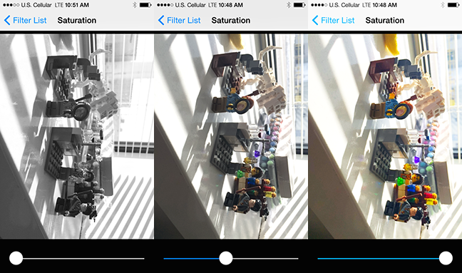
This is a fragment shader that does saturation adjustment. This shader is based off of code from the book "Graphics Shaders: Theory and Practice," which I highly recommend to anyone interested in learning more about shaders.
Saturation is the term used to describe how bright and intense a color is. A bright red sweater is far more saturated than the gloomy, gray winter skies in rural Wisconsin.
There are some optimizations we can utilize in this shader that work with the way that human beings perceive color and contrast. Generally speaking, human beings are far more sensitive to brightness than we are to color. One optimization made over the years to our compression software is to pare back the amount of memory used to store color.
Not only are humans more sensitive to brightness than color, but we are also more responsive to certain colors within the brightness spectrum, specifically green. This means that when you are calculating out ways of compressing your photos or modifying their brightness or color in some way, it’s important to put more emphasis on the green part of the spectrum, because that is the one that we respond to the most:
								varying highp vec2 textureCoordinate;

uniform sampler2D inputImageTexture;
uniform lowp float saturation;

const mediump vec3 luminanceWeighting = vec3(0.2125, 0.7154, 0.0721);

void main()
{
   lowp vec4 textureColor = texture2D(inputImageTexture, textureCoordinate);
   lowp float luminance = dot(textureColor.rgb, luminanceWeighting);
   lowp vec3 greyScaleColor = vec3(luminance);

	gl_FragColor = vec4(mix(greyScaleColor, textureColor.rgb, saturation), textureColor.w);

}
Let's go through this fragment shader line by line:
								varying highp vec2 textureCoordinate;

uniform sampler2D inputImageTexture;
uniform lowp float saturation;
Again, since this is a fragment shader that is talking to our baseline vertex shader, we do need to declare varyings for our input texture coordinate and our input image texture, in order to receive the information we need to process our filter. We do have a new uniform that we are dealing with in this example, which is saturation. Saturation amount is a parameter we are set up to receive from the user interface. We need to know how much saturation the user wants in order to present the correct amount of color.
const mediump vec3 luminanceWeighting = vec3(0.2125, 0.7154, 0.0721);
This is where we are setting up a three-component vector to store our color weighting for our luminance extraction. All three of these values must add up to 1.0 so that we can calculate the luminance of a pixel on a scale from 0.0 to 1.0. Notice that the middle number, which represents green, uses 70 percent of the available color weighting, while blue only uses a tenth of that. The blue doesn’t show up as well to us, and it makes more sense to instead weigh toward green for brightness.
lowp vec4 textureColor = texture2D(inputImageTexture, textureCoordinate);
We need to capture the color information about our specific pixel by sampling its exact coordinate within our image/texture. Instead of simply returning this value as we did with the passthrough filter, we are going to modify it and change it up a little.
lowp float luminance = dot(textureColor.rgb, luminanceWeighting);
This line will probably look unfamiliar to anyone who either never took linear algebra or who took it so long ago that dinosaurs were used to ride to school. We are using the dot product function from GLSL. If you remember using a dot symbol to multiply two numbers together in school, you’re on the right track here. The dot product is taking our vec4 containing the texture color information for the fragment, dropping the last parameter because it won’t be needed, and multiplying it by its corresponding luminance weight. Then it is taking all three of those values and adding them together to figure out the overall luminance of the pixel.
lowp vec3 greyScaleColor = vec3(luminance);
Now we are creating a vec3 that contains the luminance for all three values. If you only specify one value, the compiler knows enough to set it for each slot in that vector.
gl_FragColor = vec4(mix(greyScaleColor, textureColor.rgb, saturation), textureColor.w);
Finally, we are putting all of our pieces together. In order to determine what the new value of each color is, we are applying our handy dandy mix function that we learned about a little while ago. The mix function is taking the grayscale color we just determined, combining it with the initial texture color, and basing the ratio of the mix on the information we are getting back about the saturation level.
So here is a nice, handy shader that lets you change your image from color to grayscale and back with only four lines of code in the main function. Not too bad, huh?
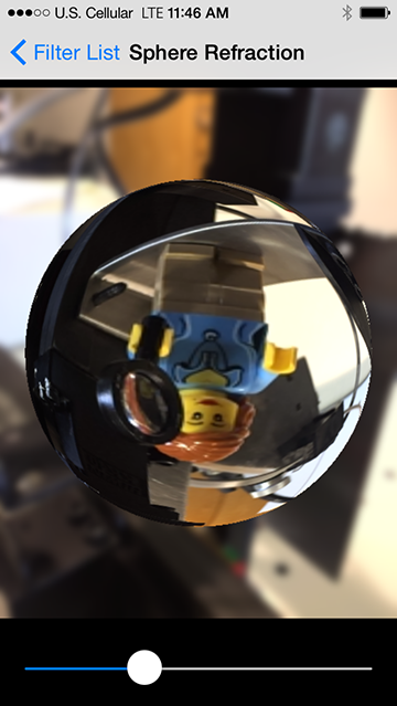
Sphere Refraction
Finally, we’re going to go over a really nifty filter that you can pull out to impress your friends and terrify your enemies. This filter makes it look like there is a glass sphere sitting on top of your image. It's going to be quite a bit more complicated than the previous ones, but I have confidence that we can do it!
								varying highp vec2 textureCoordinate;

uniform sampler2D inputImageTexture;

uniform highp vec2 center;
uniform highp float radius;
uniform highp float aspectRatio;
uniform highp float refractiveIndex;

void main()
{
    highp vec2 textureCoordinateToUse = vec2(textureCoordinate.x, (textureCoordinate.y * aspectRatio + 0.5 - 0.5 * aspectRatio));
    highp float distanceFromCenter = distance(center, textureCoordinateToUse);
    lowp float checkForPresenceWithinSphere = step(distanceFromCenter, radius);

    distanceFromCenter = distanceFromCenter / radius;

    highp float normalizedDepth = radius * sqrt(1.0 - distanceFromCenter * distanceFromCenter);
    highp vec3 sphereNormal = normalize(vec3(textureCoordinateToUse - center, normalizedDepth));

    highp vec3 refractedVector = refract(vec3(0.0, 0.0, -1.0), sphereNormal, refractiveIndex);

    gl_FragColor = texture2D(inputImageTexture, (refractedVector.xy + 1.0) * 0.5) * checkForPresenceWithinSphere;
}
Once more, with feeling...
								uniform highp vec2 center;
uniform highp float radius;
uniform highp float aspectRatio;
uniform highp float refractiveIndex;
We are bringing in a few parameters that we need in order to calculate out how much of our image is going to go through the filter. Since this is a sphere, we need a center point and a radius to calculate where the edges of the sphere are. The aspect ratio is determined by the screen size of whatever device you are using, so it can’t be hardcoded, because an iPhone has a different screen ratio than an iPad does. Our user or the programmer will decide what he or she wants the refractive index to be to determine how the refraction looks. The refractive index set in GPUImage is 0.71.
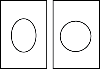
highp vec2 textureCoordinateToUse = vec2(textureCoordinate.x, (textureCoordinate.y * aspectRatio + 0.5 - 0.5 * aspectRatio));
The texture coordinates of our image are in a normalized 0.0-1.0 coordinate space. This means that instead of thinking of the phone as being 320 pixels across and 480 pixels high, the screen is one unit long and one unit wide. Since the phone is taller than it is long, we need to calculate an offset ratio for our sphere so that the sphere is round instead of oval:
highp float distanceFromCenter = distance(center, textureCoordinateToUse);
We need to calculate how far away from the center of the sphere our specific pixel is. We are using the distance() function built into GLSL, which takes the Pythagorean distance between the center coordinate and the aspect-ratio-corrected texture coordinate.
lowp float checkForPresenceWithinSphere = step(distanceFromCenter, radius);
Here is where we are going to figure out if our fragment resides within the sphere. We are checking to see how far away we are from the center of the sphere and what the radius is. If our distance is shorter than the radius, then the fragment exists within the sphere and this variable is set to 1.0. If, however, the distance from the center is longer than the radius, the fragment does not live within the sphere and this gets set to 0.0:
distanceFromCenter = distanceFromCenter / radius;
Now that we have determined which pixels exist within the sphere, we are going to move on to calculating what to do with the ones that do exist in the sphere. Again, we need to normalize our distance from the center. Rather than creating a whole new variable, which adds to the overhead in our program, we are going to reset the distanceFromCenter variable. By dividing it by the radius, we are making our math calculations easier in the next few lines of code.
highp float normalizedDepth = radius * sqrt(1.0 - distanceFromCenter * distanceFromCenter);
Since we are trying to emulate a glass sphere, we need to figure out how “deep” the sphere is. The virtual sphere, for all intents and purposes, is extending a distance up from the image surface toward the viewer in the z-axis. This is going to be used to help the computer figure out how to model the pixels that exist within the sphere. Also, since a sphere is round, there will be different depths for the sphere depending upon how far away you are from the center. The center of the sphere will refract light differently than the edges, due to the different orientations of the surface:
highp vec3 sphereNormal = normalize(vec3(textureCoordinateToUse - center, normalizedDepth));
Again, we are back to normals, huzzah. To describe the orientation of the sphere surface at a point, we take the distance of the current pixel from the center of the sphere in X and Y, and combine those components with the sphere depth we calculated. We then normalize the resulting vector to have a length of one.
Think about when you are using something like Adobe Illustrator. You create a triangle in Illustrator, but it's too small. You hold down the option key and you resize the triangle, except now it's too big. You then scale it down to get it to be the exact size you want:
highp vec3 refractedVector = refract(vec3(0.0, 0.0, -1.0), sphereNormal, refractiveIndex);
refract() is a fun GLSL function. refract() is taking in the sphere normal we just created and using the refractive index to calculate how light passing through a sphere of this type would look at any given point.
gl_FragColor = texture2D(inputImageTexture, (refractedVector.xy + 1.0) * 0.5) * checkForPresenceWithinSphere;
Finally, after jumping through all these hoops, we have gathered together all of the pieces we need to figure out what color to use for the fragment. The refracted light vector is used to find which location on the input image to read from, but because the coordinates in that vector range from −1.0 to 1.0, we adjust that to lie within the 0.0–1.0 texture coordinate space.
We then multiply our effect by the value we got from our sphere bounds check. If our fragment doesn’t lie within the sphere, a transparent pixel (0.0, 0.0, 0.0, 0.0) is written. If the fragment is present within the sphere, the effect is applied and the calculated color returned. This allows us to avoid expensive conditional logic for the shader.
Debugging Shaders
Debugging shaders is not a straightforward task. In your normal program, if the program crashes, you can set a breakpoint. That isn't really possible to do on an operation that gets called in parallel millions of times a second. It also isn't feasible to use printf() statements in your shaders to debug what is going wrong, because where would the output even go? Given that your shaders seem to be living in a black box, how do you crack them open to find out why they aren't working?
You have one output at your disposal: our old friend gl\_FragColor. gl\_FragColor gives you an output that, with a little lateral thinking, you can use to debug your code.
All colors you see on the screen are represented by a series of numbers, which are a percentage of the amount of red, green, blue, and opacity each individual pixel contains. You can use this knowledge to test each part of your shader as you construct it to make sure that it is performing the way you would like. Instead of getting back a printed value, you would get back a color with a specific associated value that you can reverse engineer.
If you want to know the value of one of your variables that is between zero and one, you can set it to part of the vec4 that gets passed to the gl\_FragColor. Let's say you set it to the first part, which is the red value. That value will be converted and rendered to the screen, at which point you can examine it to determine what the original value was that was passed in.
You can then capture these values in a couple of ways. The output image from your shader could be captured and written to disk as an image (preferably in an uncompressed format). This image could then be pulled into an application like Photoshop and the pixel colors examined.
For faster turnaround, you could render your image to the screen in an OS X application, or an iOS one running in the Simulator. To analyze these rendered views, there is a tool included in your Utilities folder in your Applications folder called "Digital Color Meter." If you hover your mouse over any pixel on your desktop, it will show you the exact RGB component of that pixel. Since RGB values in Digital Color Meter and Photoshop are from 0 to 255 instead of 0 to 1, you need to divide the specific value you want by 255 to get an approximate value of what the initial passed-in value was.
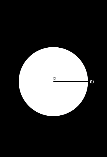
Let's look back at our sphere refraction shader. We wouldn't want to try to write the whole shader without doing any debugging on it. We have the specific chunk of code to determine if the pixel we are currently looking at is within the circle or not. That block of code ends with a step() function that sets the value of a pixel to either 0.0 or 1.0.
If you passed a vec4 to the gl\_FragColor, where the red value was whatever the step() function value was, and the other two colors were set to 0.0, you should see a red circle on a black screen if your code is working properly. If the whole screen is either black or red, then something has gone terribly wrong.
Performance Tuning
Performance tuning and profiling are incredibly important things to do, especially if you are trying to target your application to run smoothly on older iOS devices.
Profiling your shader is important, because you can't always be sure how performant something will be. Shader performance changes in nonintuitive ways. You might find a great optimization on Stack Overflow that does nothing to speed up your shader because you didn't optimize where the actual bottleneck was in your processing code. Even switching a couple of lines of code in your project can vastly increase or decrease the amount of time it takes for your frame to render.
When profiling, I recommend measuring frame rendering time, rather than focusing on frames per second (FPS). Frame rendering time increases or decreases linearly with the performance of your shader, which makes it easy to see the impact you're having. FPS is the inverse of frame time, and it can be harder to understand when tuning. Lastly, if you're capturing from the iPhone's video camera, it will adjust incoming FPS depending upon the lighting in your scene, which can lead to incorrect measurements if you rely on that.
The frame rendering time is the amount of time it takes for the frame to begin processing until it completely finishes and is rendered to the screen or to a final image. Many mobile GPUs use a technique called "deferred rendering," where rendering instructions are batched up and executed only as needed. Therefore, it's important to measure the entire rendering operation, rather than operations in the middle, because they may run in a different order than you expect.
Optimizations can also vary wildly from device to device, desktop, and mobile. You may need to profile on multiple classes of devices. For example, the GPUs in mobile iOS devices have grown increasingly more powerful. The CPU on an iPhone 5S is approximately 10 times faster than the CPU on the iPhone 4, however its GPU is hundreds of times faster.
If you are testing your applications on devices with an A7 chip or higher, you are going to get vastly different results than you would with an iPhone 5 or lower. Brad Larson profiled how long a Gaussian Blur took on various iOS devices and has clearly demonstrated a dramatic leap forward in processing times on newer devices:
iPhone Version | Frame Rendering Time in Milliseconds -------------- | ------------------------------------ iPhone 4 | 873 iPhone 4S | 145 iPhone 5 | 55 iPhone 5S | 3
There is a tool that you can download, Imagination Technologies PowerVR SDK, that will profile your shader and let you know the best- and worst-case performance for your shader rendering. It's important to get the number of cycles necessary to render your shader as low as possible to keep your frame rate high. If you want to hit a target of 60 frames per second, you only have 16.67 milliseconds to get all of your processing done.
Here are some easy ways to help you hit your target:
-
Eliminate conditional logic. Sometimes it's necessary to include conditional logic, but try to keep it to a minimum. Using workarounds like the
step()function can help you avoid expensive conditional logic in your shaders. -
Reduce dependent texture reads. Dependent texture reads occur when a texture is sampled in a fragment shader from a texture coordinate that wasn't passed in directly as a varying, but was instead calculated in the fragment shader. These dependent texture reads can't take advantage of optimizations in caching that normal texture reads do, leading to much slower reads. For example, if you want to sample from nearby pixels, rather than calculate the offset to the neighboring pixel in your fragment shader, it's best to do this calculation in the vertex shader and have the result be passed along as a varying. A demonstration of this is present in Brad Larson's article, in the case of Sobel edge detection.
-
Make your calculations as simple as possible. If you can avoid an expensive operation and get an approximate value that is good enough, you should do so. Expensive calculations include calling trigonometric functions (like
sin(),cos(), andtan()). -
Shift work over to the vertex shader, if it makes sense. Our previous talk about dependent texture reads is a situation where it would make sense to move texture coordinate calculations to the vertex shader. If a calculation would have the same result across your image, or would linearly vary across it, look at moving that calculation into the vertex shader. Vertex shaders run once per vertex, whereas fragment shaders execute once per pixel, so a calculation performed in the former will run fewer times.
-
Use appropriate precision on mobile devices. On certain mobile devices, it can be much faster to work with lower precision values in vectors. The addition of two
lowp vec4s can often be done in a single clock cycle on these devices, where the addition of twohighp vec4s can take four clock cycles. This is less important on desktop GPUs and more recent mobile GPUs, though, as they don't have the same optimizations for low precision values.
Conclusions and Resources
Shaders seem kind of scary at first, but they are nothing more than modified C programs. Everything involved in creating a shader is stuff that most of us have dealt with at one point or another, just in a different context.
One thing I would highly recommend for anyone trying to get into shaders is to refamiliarize yourself with trigonometry and linear algebra. The biggest stumbling block I encountered when working with this was that I didn't remember a lot of the math I learned in high school, because I hadn't used it in a really long time.
There are some books I would recommend if your math is a little rusty:
There are also countless books out there about GLSL and how some very specific shaders were created by prominent members of our industry:
Also, again, GPUImage is an open-source resource to get a look at some really cool shaders. One good way to learn about shaders is to take a shader you find interesting and go through it line by line, looking up any part of it that you don't understand. GPUImage also has a shader designer application on the Mac side that lets you test out shaders without having to set up the OpenGL code.
Learning how to effectively implement shaders in your code can give you a huge performance boost. Not only that, but shaders also allow you to do things that were not possible before.
Learning shaders takes some tenacity and some curiosity, but they aren't impossible. If a 33-year-old recovering journalism major could confront her math fear to tackle shaders, so can you.